

많은 분들께서 초자류 주문해주실 때 이 온도에서 가능한지 많이 여쭤보시는데요!
주로 고온에서 사용할 목적이 있으신 분들이 많이 여쭤보시는데요!
보통 실험실에서는 파이렉스 유리를 많이 사용합니다.
각 유리 종류에 따른 사용온도는 아래표를 참고 해주세요^^

1. 특징
열충격이나 온도의 급격한 변화에 높은 저항력을 가진 유리로서 soda-lime유리에 비해 높은 온도에서 작업이 가능하고 화학적 내구성을 지닌 특수유리이다. 대표적인 것이 파이렉스글라스(Pyrex Glass)이며 SiO2(81%), B2O3(12%)를 함유하고 열팽창율은 보통유리에 1/3정도이다. 내열충격성은 Quartz(석영유리)에 미치지 못하나 Quartz보다는 대량생산이 가능하고 성형성이 좋은 저팽창성의 유리로서 이화학용 용기나, 관 반도체 장비부품으로도 많이 사용되고 있다.
Safety Sight Glass (안전시창유리) & High Temperature Glass (고온고압유리)
| Glass Name 품 목 |
Working Temp℃ 상용사용온도 |
Max Temp℃ 최대사용온도 |
Thickness 두 께 |
|---|---|---|---|
| Tempered Glass(강화유리) | 220℃ | 250℃ | 3t ∼25t |
| Borosilicate(Pyrex, Borofloat) | 450℃ | 500℃ | 1t ∼ 30t |
| 벽난로유리(세라믹유리) | 700℃ | 800℃ | 3, 4, 5t |
| Vycor | 900℃ | 1200℃ | 1t ∼ 50t |
| Fused silica(석영유리) | 1000℃ | 1300℃ | 1t ∼ 10t |
| Level Gage Glass(수면게이지) | 250℃ | 320℃ | - |
| Mica sheet(운모) | - | - | 0.2t |
2. Size별 Spec
Disc sight glasses Available sizes
Data sheet
| Dimensions d1 × s (mm) |
Insepection aperture d2(mm) |
Permissible Pressure in bar |
Test pressure in bar acc. to formula |
Dimensions d1 × s (mm) |
Insepection aperture d2(mm) |
Permissible Pressure in bar |
Test pressure in bar acc. to formula |
|---|---|---|---|---|---|---|---|
| 30×15 | 20 | 200 | 1600 | 95×15 | 75 | 25 | 200 |
| 35×7 | 25 | 25 | 200 | 100×10 | 80 | 8 | 64 |
| 40×12 | 30 | 50 | 400 | 100×15 | 80 | 16 | 128 |
| 45×10 | 32 | 40 | 320 | 100×20 | 80 | 25 | 200 |
| 45×12 | 32 | 50 | 400 | 100×25 | 80 | 40 | 320 |
| 50×10 | 35 | 25 | 200 | 125×15 | 100 | 10 | 80 |
| 50×12 | 35 | 40 | 320 | 125×20 | 100 | 16 | 128 |
| 55×10 | 40 | 25 | 200 | 125×25 | 100 | 25 | 200 |
| 60×10 | 45 | 16 | 128 | 125×30 | 100 | 40 | 320 |
| 60×12 | 45 | 25 | 200 | 150×15 | 125 | 8 | 64 |
| 60×15 | 45 | 40 | 320 | 150×20 | 125 | 10 | 80 |
| 63×8 | 48 | 10 | 80 | 150×25 | 125 | 16 | 128 |
| 63×10 | 48 | 16 | 128 | 150×30 | 125 | 25 | 200 |
| 63×12 | 48 | 25 | 200 | 175×20 | 150 | 10 | 80 |
| 63×15 | 48 | 40 | 320 | 175×25 | 150 | 16 | 128 |
| 70×12 | 55 | 16 | 128 | 175×30 | 150 | 25 | 200 |
| 70×15 | 55 | 25 | 200 | 200×20 | 175 | 8 | 64 |
| 80×10 | 65 | 10 | 80 | 200×25 | 175 | 10 | 80 |
| 80×12 | 65 | 16 | 128 | 200×30 | 175 | 16 | 128 |
| 80×15 | 65 | 25 | 200 | 250×25 | 225 | 8 | 64 |
| 80×20 | 65 | 40 | 320 | 250×30 | 225 | 10 | 80 |
| 90×10 | 70 | 10 | 80 | 265×30 | 225 | 8 | 64 |
3. PROCESS PLANT IN BOROSILICATE GLASS 3.3
Sigma borosil glass plants, pipelines & components are fabricated as per following international standards.
BS EN 12585:1999 – Glass plant, pipeline & fittings compatibility & interchangeability.
BS EN 1595:1997 – General rules for design, manufacture & testing.
The full range of standard components & associated equipment available is described in the following sections of the catalog.
4. CHEMICAL COMPOSITION OF BOROSILICATE GLASS 3.3
| COMPONENT | % BY WEIGHT |
|---|---|
| SiO2 | 80.6 |
| B2O3 | 12.5 |
| Na2O | 4.2 |
| Al2O3 | 2.2 |
| Others | 0.5 |
PROPERTIES OF BOROSILICATE GLASS 3.3
The very wide use of this material throughout the world in the chemical and pharmaceutical industries as well as many other allied areas, is mainly due to its chemical and thermal properties (see also ISO 3585) together with a great number of other benefits that distinguish borosil glass 3.3 from other materials of construction. These include special properties e.g
- Smooth non-porous surface
- Transparency
- Outstanding corrosion resistance
- No adverse physiological properties
- Neutral smell and taste
- Non-flammability
- Catalytic inertness.
CHEMICAL RESISTANCE
Borosilicate glass 3.3 is resistant to corrosion by almost all chemicals. This makes its resistance more comprehensive than that of other well-known materials. It is highly resistant to water, saline solutions, organic substances, halogens & many acids. There are only a few chemicals which cause noticeable corrosion of glass namely, hydrofluoric acid, concentrated phosphoric acid & strong caustic solutions at elevated temperature.
The curves in fig .1 show a maximum corrosion for different acids in the concentration range between 4 and 7 N (HCI for example at the azeotrope with 20.2 wt%). Above that reaction, speed decreases markedly so that the eroded layer amounts to only a few thousandths of millimeter after some years. There is, therefore, the justification for referring to borosilicate glass 3.3 as an acid-resistant material.
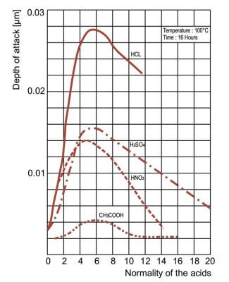
Fig. 1
Acid attack on borosilicate glass 3.3 as a function of concentration
It can be seen from the corrosion curves in fig .2 that the attack on the glass surface initially increase as the concentration of the caustic solution increases but after exceeding a maximum it assumes a virtually constant value. Rising temperatures increase the corrosion, While at low temperatures the reaction speed is so low that reduction of the wall thickness is hardly detectable over a number of years.
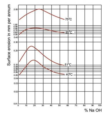
Fig. 2
Alkali attack on borosilicate glass 3.3 as a function of temperature & Concentration
OPTICAL PROPERTIES
Borosilicate glass 3.3 shows no appreciable light absorption in the visible range of the spectrum, thus it is clear & colorless. Transmission of UV light is significant in the middle spectrum compared to normal glass. Borosilicate glass 3.3 is ideally suited for photochemical reactions such as chlorination & sulphochlorination.
THERMAL SHOCK
Quick changes in temperature across the walls of glass components should be avoided during operation both indoors and outside. They result in increased thermal stress in the glass, which as described above, has an adverse effect on the permissible operating pressure of the plant components. Although it is not possible to give a definite figure applicable to all the operating conditions likely to be encountered in practice, a maximum permissible thermal shock of 120°C can be taken as a general guide.
PERMISSIBLE OPERATING TEMPERATURE
Borosilicate glass retains its mechanical strength and will deform only at a temperature which approaches its strain point. The practical upper limit for operating temperature is much lower and is controlled by the temperature differentials in the glass which depends on the relative temperature of the contents of the equipment and the external surroundings. Provided Borosilicate glass is not subject to rapid change in temperature, creating undue thermal shock, it can be operated safely at temperature up to 250°C
It must be realized that in complete plants, composed not only of borosilicate glass, but also include other materials such as PTFE. The recommended max. Operating temperature is 200°C. Operating temperatures may have to be modified so as to compensate for the effects of other factors such as pressure, thermal cycling, rapid heating & cooling etc.
At sub-zero temperature, the tensile strength of borosilicate glass tends to increase and equipment can be used safely at a temperature as low as – 50°C for Sigma Flat Buttress end components.
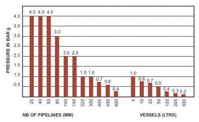
PERMISSIBLE OPERATING PRESSURE
The permissible internal operating working pressure depends on the nominal diameter size of glass components and external temperature. The maximum working pressure for a complete glass plant is determined by the lowest rated components in the system. All glass components are suitable at full vacuum over the entire temperature range. Bar g is a measure of absolute pressure.
COMPOSITE MATERIALS
The last two decades have seen further developments of, particular corrosion resistant plant construction materials. Typical examples of these are PTFE, tantalum, titanium, graphite and of course, borosilicate 3.3 glass.
The combination of different corrosion resistant materials with the utilization of the specific advantages of each permits both safe and economic construction.
Borosilicate glass/PTFE
Borosilicate Glass with PTFE is of particular importance for the construction of glass installation. For example, In Seals, Bellows, Stirrers, Heat Exchangers, Column Inserts etc.
PTFE is used with Glass because of its excellent mechanical & thermal properties. They have near universal fluid compatibility. Wear life when compared with others is very low. Particularly PTFE is maintenance free and has cryogenic stability with the non-wetting property. Service temperature of PTFE is considered as – 50°C to + 200°C
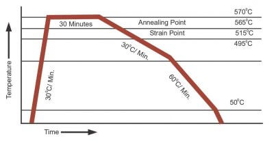
ANNEALING
Annealing of glass is the process where the glass is heated and kept for a defined period of time to relieve internal stresses.
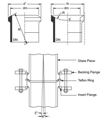
SIGMA FLAT BUTTRESS END
The glass process plant and pipeline components detailed in this catalog have standard Sigma Flat buttress end which is interchangeable with any international standard. We can also supply Ball & socket (Spherical end forms), and tapered type buttress end as per international standard on request.
The major dimensions of the Sigma flat buttress ends can be found in the table below, in conjunction with the illustrations alongside.
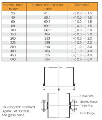
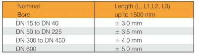
LENGTH & TOLERANCE OF GLASS COMPONENTS:
The tolerances on length L together with dimensions L1, L2 and L3 of components, unless otherwise specified for given components in this catalog.
FLANGE DIMENSIONS BALL SOCKET
(as per International Standard)
| D2 | R | ||
|---|---|---|---|
| DN | MM | DM | MM |
| 15 | 30 | 23 | 18 |
| 25 | 44 | 34 | 25 |
| 40 | 62 | 51 | 40 |
| 50 | 76 | 63 | 50 |
| 80 | 110 | 96 | 80 |
| 100 | 130 | 116 | 100 |
| 150 | 184 | 169 | 150 |
| 200 | 233 | 220 | 200 |
| 300 | 338 | 321 | 300 |
| 400 | 465 | 435 | – |
| 450 | 526 | 492 | – |
| 600 | 684 | 646 | – |
Coupling with standard Ball-Socket end glass piece Articulation is 0 possible to a maximum of 3, depending on the diameter
JACKETED COMPONENTS
SIGMA can supply jacketed version of all major components listed in the catalog, such as pipe and fitting, column components, heat exchangers and vessels. The glass jacket is sealed onto the component either by fusing, by silicon rubber or in a combination of both. The jacketed components help in saving energy by minimizing heat loss, and to maintain the product characteristics at the desired temperatures.
The permissible operating temperature
for the inner component:
| form (-) 40° C component: |
|
| The permissible operating temperature for jacket: |
form (-) 40° C to 180° C |
| The permissible operating pressure: | 0.5 kg/cm²g to Full Vacuum |
STATIC ELECTRICITY
Electrostatic charge generation
Electrostatic charge generation in glass vessels and piping systems occurs due to:-
* The agitation of a low conductivity fluid in a vessel, or The flow of a low conductivity liquid through a piping system.
* The charge generated is retained in the fluid and due to the low conductivity cannot be dissipated (even if the fluid is in contact with a high conductivity pure metal vessel /pipe wall )
Charge generation will occur whether the vessel/ pipework is glass or of metal construction.
The charge generated depends on the actual operating conditions. For more information contact our technical department.
댓글 0
다른 포스트 둘러보기
PVC (Polyvinyl chloride)는 구조가 폴리에틸렌과 유사하지만 각 단위에는 염소 원자가 포함되어 있습니다. 염소 원자는 일부 용매에 취약하게 만들지 만 많은 응용 분야에서 화학적 내성을 더욱 강화합니다. PVC는 오일 (에센셜 오일 제외)에 대한 저항성이 매우 우수하고 대부분의 가스에 대한 투과성이 매우 ...
오늘은 대표적인 멸균법중의 하나인 EO가스 멸균에 대해서 알아볼텐데요! 아래 사진은 랩실에서 볼 수있는 EO가스입니다.
많은 분들께서 초자류 주문해주실 때 이 온도에서 가능한지 많이 여쭤보시는데요! 주로 고온에서 사용할 목적이 있으신 분들이 많이 여쭤보시는데요! 보통 실험실에서는 파이렉스 유리를 많이 사용합니다. 각 유리 종류에 따른 사용온도는 아래표를 참고 해주세요^^ 1. 특징 열충격이나 온도의 급격한 변화에 높은 저항력을 가진 유리로서 so...
폴리에틸렌 및 폴리 프로필렌과 마찬가지로 폴리 프로필렌 공중 합체는 폴리올레핀으로 분류되며 고 분자량 탄화수소입니다. PPCO는 에틸렌과 프로필렌의 반복 된 순서를 갖는 본질적으로 선형 공중 합체이며 두 중합체의 장점 중 일부를 결합합니다. PPCO는 오토 클레이브 가능하고 폴리 프로필렌의 고온 성능을 제공하며 폴리에...
폴리에틸렌과 마찬가지로 폴리 프로필렌은 폴리올레핀으로 분류되며 고 분자량 탄화수소입니다. 폴리 프로필렌의 화학 구조는 폴리에틸렌과 유사하지만 사슬의 각 단위에는 메틸기가 부착되어 있습니다. 모든 폴리올레핀과 마찬가지로 폴리 프로필렌은 독성이없고 오염되지 않으며 물보다 가볍습니다. PP는 자연적으로 유백색 반투명이지만 착...